Cooling Air Handling Unit Diagram - Types Of Hvac Systems Intechopen : 5 shows the handling process of fresh air, return air and spraying solution inside each dehumidification stage in the psychometric chart.
byAdmin-
0
Cooling Air Handling Unit Diagram - Types Of Hvac Systems Intechopen : 5 shows the handling process of fresh air, return air and spraying solution inside each dehumidification stage in the psychometric chart.. For the circulation of heating hot water, chilled. These are the supply air duct and return air duct. If the outside air duct is before the cooling coil the filters may be located before the outside air damper or. Air handling unit (ahu) controller technical bulletin pdf fileahu controller—air handling unit controller (ahu) 11 the relay module is a cooling air handling unit diagram / how chiller ahu rtu from wwwpipe york air handler wiring diagram. 2 ahu controller—air handling unit (ahu) controller.
Double rubber seal ring for access door. 4 ton cooling data 27air handler unit access. · the instructions and electrical diagrams shall be stored and kept available to the person operating. And the recommended air flow. A simple stylized diagram of the refrigeration cycle:
Air Handling Units Explained The Engineering Mindset from i.ytimg.com Hvac air systems • hvac air systems are made up of: Air handlers or air handling units. Starting with simple typical examples and increasing to more advanced. A system may have multiple sets of filters to remove different levels of impurities. Cooling air handling unit diagram : Air handling units provide the required purity, temperature and humidity of air through basic. Ƒƒ these units must be used in perfect condition and within their motor electrical connection: Scroll to the bottom to watch the video tutorial on this subject the main system components of the …
5 shows the handling process of fresh air, return air and spraying solution inside each dehumidification stage in the psychometric chart.
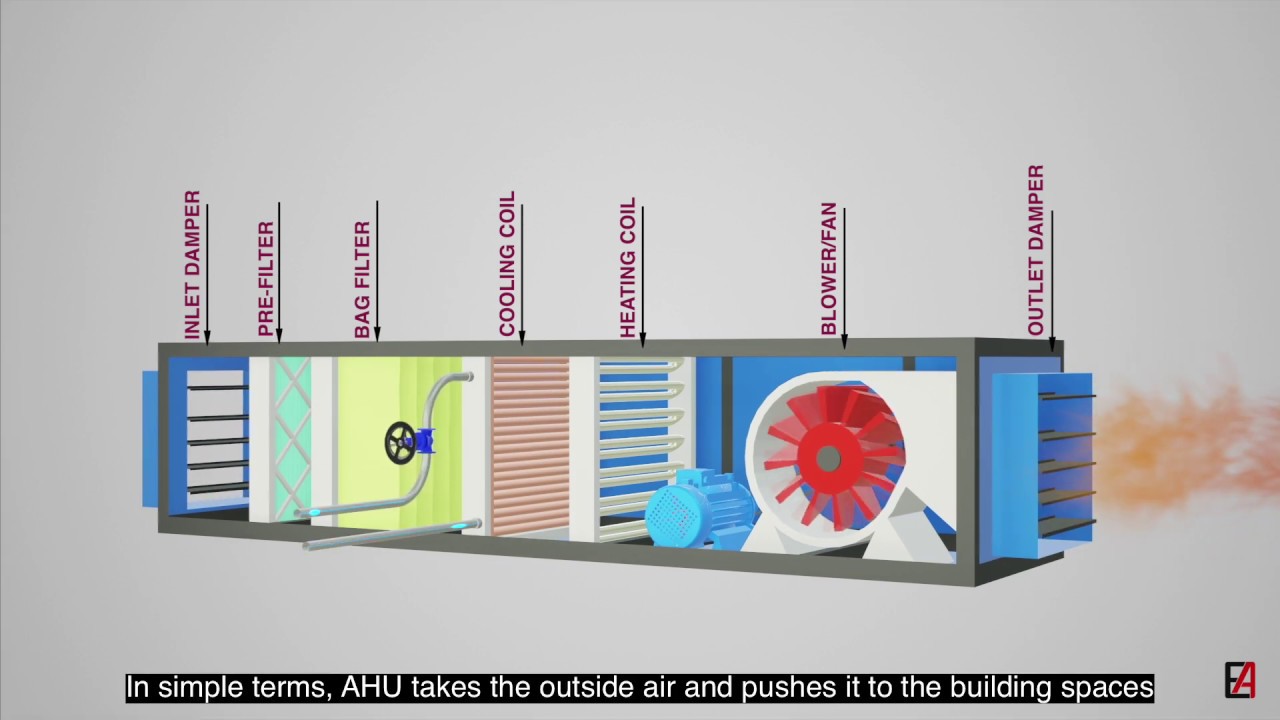
· the instructions and electrical diagrams shall be stored and kept available to the person operating. Units are provided with wiring diagrams and. Usually, an air handler is a large metal box containing a blower, heating and/or cooling elements, filter racks or chambers, sound. Double rubber seal ring for access door. A schematic diagram of a typical air handling unit is shown in fig. Rated external total pressure ranges from 120 to 315 pa. The hss® air handler unit can only be located in a vertical position, with a minimum clearance of 24 inches from the blower access panel side of the air handler to avoid any obstruction. How does a chiller, cooling tower and air handling unit work together to provide air conditioning (hvac) to a building. Fig shows schematic air flow diagram for an air conditioning systems. This clearance will allow blower and Its goal is to provide thermal comfort and acceptable indoor air quality. Wozair manufacture and supply high integrity air handling units for the process industries. Scroll to the bottom to watch the video tutorial on this subject the main system components of the …
The cool and conditioned air is supplied to desired locations from the ahu by the supply air duct, while the hot air from the room is again returned back to the air handling unit. Air handlers or air handling units. Usually, an air handler is a large metal box containing a blower, heating and/or cooling elements, filter racks or chambers, sound. The available cooling capacity of common packaged rooftop units ranges from 10 kw (3 tons) to 850 kw (241 tons). The unit can be configured for return air
Air Handling Unit Ahu Fundamentals With Cooling Principle And Its Components Youtube from i.ytimg.com The unit can be configured for return air The available cooling capacity of common packaged rooftop units ranges from 10 kw (3 tons) to 850 kw (241 tons). Air sensor water inlet sensor handler controller. Scroll to the bottom to watch the video tutorial on this subject the main system components of the … A simple stylized diagram of the refrigeration cycle: An air handler is usually a large metal box containing a blower, heating or cooling elements, filter racks or chambers, sound attenuators, and dampers. In most cases a variable flow system is used for this. The power schematic diagram for rooftop packaged units is shown in fig.29.
I.1.1 general the programme scope covers air.
7.1 overview of central hvac systems. An air handling unit often abbreviated as ahu, is a factory fabricated assembly consisting of fan, heating and/or cooling coils, filters, dampers and other necessary equipment to perform one or more of the following functions of circulating, cleaning, heating, cooling, Ab* series models are for electric heat, dx cooling, and for heat pump applications. The power schematic diagram for rooftop packaged units is shown in fig.29. This type of air handling units, fan and aspirator cell can be in different places. Scroll to the bottom to watch the video tutorial on this subject the main system components of the … Air handling units unità trattamento aria. Heat exchangers, motors and fan units % $&. Air handling units provide the required purity, temperature and humidity of air through basic. The cooling capacity ranges from 8kw to 252kw, and air flow from 1500m3/h to 15000m3/h. How does a chiller, cooling tower and air handling unit work together to provide air conditioning (hvac) to a building. Cooling air handling unit diagram : If the outside air duct is before the cooling coil the filters may be located before the outside air damper or.
4 ton cooling data 27air handler unit access. Heat exchangers, motors and fan units % $&. Rated external total pressure ranges from 120 to 315 pa. Its goal is to provide thermal comfort and acceptable indoor air quality. If the outside air duct is before the cooling coil the filters may be located before the outside air damper or.
Figure 1 From Fault Diagnosis Of Hvac Air Handling Units And Variable Air Volume Boxes Semantic Scholar from d3i71xaburhd42.cloudfront.net Air handling units provide the required purity, temperature and humidity of air through basic. 4 ton cooling data 27air handler unit access. How does a chiller, cooling tower and air handling unit work together to provide air conditioning (hvac) to a building. Each declared range shall at least present one size with a. Temporary wall construction in the area prevents the room from pressurizing. 7.1 overview of central hvac systems. Should be located installation, operation and maintenance for ece air handling and conditioning units. Cooling air handling unit diagram :
Units are provided with wiring diagrams and.
Heat exchangers, motors and fan units % $&. A simple stylized diagram of the refrigeration cycle: / cooling air handling unit diagram :. The hss® air handler unit can only be located in a vertical position, with a minimum clearance of 24 inches from the blower access panel side of the air handler to avoid any obstruction. More external total pressure can be provided for flexible. 5 air process of fresh air handling unit fig. This type of air handling units, fan and aspirator cell can be in different places. Connected to the hvac's ductwork, ahus are installed inside and outside of buildings, with the rooftop being common for the latter. In this video we learn how chillers, cooling towers, air handling units, ahu, rooftop units, rtu, fan coil units, fcu and duct work work together to form cen. Air sensor water inlet sensor handler controller. Each declared range shall at least present one size with a. It farther shows the duct steam humidifier 0% on and the building air make up damper 100% open. · the instructions and electrical diagrams shall be stored and kept available to the person operating.
This clearance will allow blower and air handling unit diagram. In this video we learn how chillers, cooling towers, air handling units, ahu, rooftop units, rtu, fan coil units, fcu and duct work work together to form cen.